
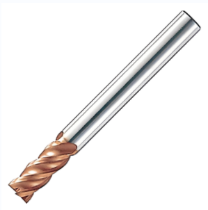
The shanks of solid carbide end mills are primarily straight cylindrical shanks (see Figure A) and cylindrical shanks with a flat surface (commonly known as "side lock" or "side lock shank").
Straight Shank
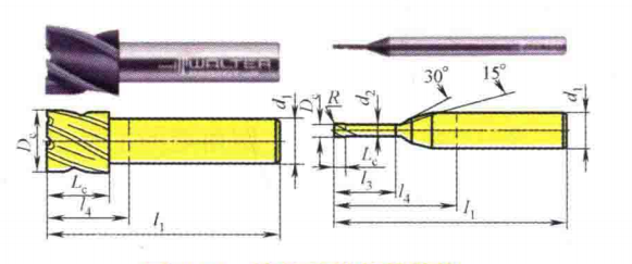
The shank of a straight shank milling cutter is a complete cylinder, therefore, in terms of the shank itself, this type of cutter has very good precision and concentricity when clamped. The term "straight shank" does not mean that the shank diameter size and the working part diameter size D are the same basic dimensions. Sometimes, the working part diameter size D is larger than the shank diameter size d (D > d), which is called "undercut"; while in another case, the working part diameter size D is smaller than the shank diameter size d (D < d), which is called "overcut", as shown in Figure B.
When using a general clamping method (such as a collet chuck) to hold a straight shank, the primary reliance is on frictional force. As a result, there may sometimes be insufficient clamping force. If a straight shank structure is used with a milling cutter that has a large helix angle and generates significant axial force, it is relatively easy for the cutter to be pulled out of the chuck, especially when an "overcut" phenomenon occurs.
Therefore, when using a milling cutter with a large helix angle for side milling or slot milling, a more secure type of chuck should be used, such as a high-precision collet or a collet with a safety lock (SafeLock). Alternatively, a cylindrical shank with a flat surface, as introduced below, can also be employed.
Flat-Faced Cylindrical Shank
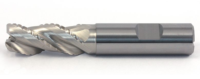
Another main type of shank structure for solid carbide end mills is the cylindrical shank with a flat surface (see Figure C). The driving force of a milling cutter with a flat surface does not rely on friction, but rather on the driving force provided by the flat surface, thus preventing slippage. At the same time, the flat surface also restricts the milling cutter in the axial direction, preventing the "tool drop" phenomenon when retracting the tool.
This structure can vary according to the diameter of the shank. As shown in Figure C, there can be a single flat surface, or for larger sizes, there can be two flat surfaces. These are not two different standards, but rather two types of a standard tool shank for different size ranges. However, the structure with two flat surfaces is only used when the shank diameter is 25mm or greater. Therefore, milling cutters with a diameter of 20mm or less are essentially all single flat surface structures.
Due to the presence of the flat surface, theoretically, the center of gravity of the tool holder will have a slight deviation from the axis of the tool holder, and this deviation is on the side away from the pressure surface. This point will be used in the analysis below.
Although this structure can avoid some issues associated with the straight shank driven by friction, it also has three drawbacks.
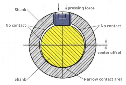
1) The first drawback is poor coaxiality between the tool and the tool holder. There is always a slight gap theoretically between the cylindrical shank with a flat surface and the cylindrical hole used for clamping. When the cylindrical shank is inserted into the round hole of the tool holder and tightened with a screw, the tool is pressed to one side, and the clamping state is shown in Figure D. The axis of the tool will deviate from the axis of the tool holder, causing misalignment between the tool and the tool holder.
2) The second drawback is poor contact rigidity. As can be seen from Figure D, after the milling cutter is clamped, there is a narrower contact band on one side of the milling cutter and the tool holder, while the other side does not make contact. The size of this contact band and the size of the gap vary depending on the gap between the two. If the contact band is too narrow and the gap is too large, it can lead to deformation of the contact surface, which can adversely affect the interchangeability of the tool and tool holder.
3) The third drawback is poor dynamic balance. In addition to the slight eccentricity of the tool holder's center of gravity from the tool holder's axis mentioned earlier, and the imbalance caused by this flat structure itself, the clamping process exacerbates this imbalance. This is very unfavorable for high-speed machining.