


| HRC | Coating | picture |
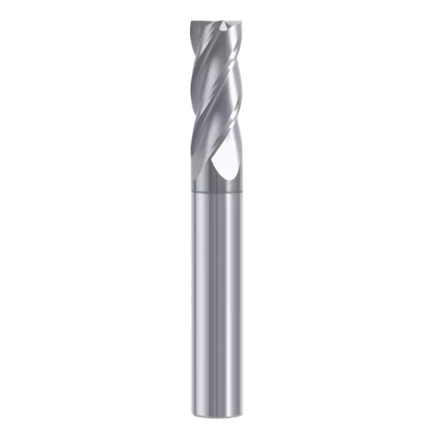
| 55° | DCL colorful | 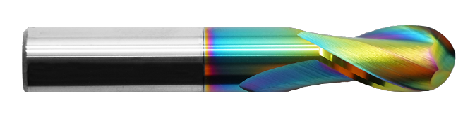 |
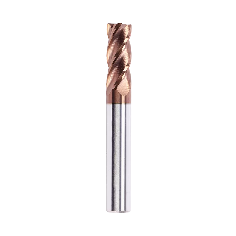
| 55° | antique steel color | 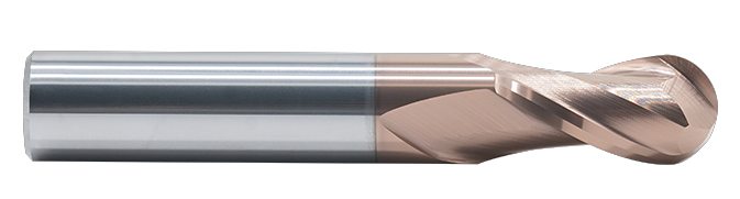 |
| 56° | / | 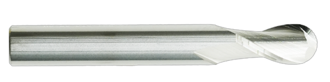 |
| 56° | Nano antique steel color | |
| 58° | Nano black | 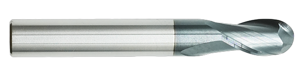 |
| 60° | Nano blue | 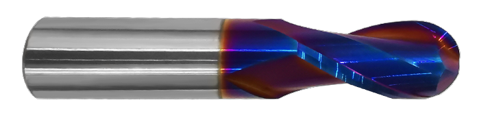 |
| 62° | Nano black | |
| 65° | Nano blue | 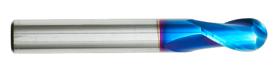 |
(HRC55°/56°/58°/60°/62°/65°) 2Flute ball milling cutter model specification table:
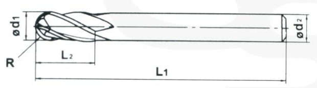
R=Radius d1=Flute Diameter d2=Shank Diameter L1=Overall Length L2=Flute Length
| specifications | Radius(mm) | Flute Length(mm) | Shank Diameter(mm) | Overall Length(mm) |
| R0.5*2*D4*50L | 0.5 | 2 | 4 | 50 |
| R0.75*3*D4*50L | 0.75 | 3 | 4 | 50 |
| R1*4*D4*50L | 1 | 4 | 4 | 50 |
| R1.25*6*D4*50L | 1.25 | 6 | 4 | 50 |
| R1.5*6*D4*50L | 1.5 | 6 | 4 | 50 |
| R1.5*6*D3*50L | 1.5 | 6 | 3 | 50 |
| R1.5*6*D3*75L | 1.5 | 6 | 3 | 75 |
| R1.5*6*D3*100L | 1.5 | 6 | 3 | 100 |
| R1.75*7*D4*50L | 1.75 | 7 | 4 | 50 |
| R1*4*D2*50L*2F | 1 | 4 | 2 | 50 |
| R2*8*D4*50L | 2 | 8 | 4 | 50 |
| R2*8*D4*75L | 2 | 8 | 4 | 75 |
| R2*8*D4*100L | 2 | 8 | 4 | 100 |
| R2.5*10*D6*50L | 2.5 | 10 | 5 | 50 |
| R2.5*10*D5*50L | 2.5 | 10 | 5 | 75 |
| R2.5*10*D5*75L | 2.5 | 10 | 5 | 75 |
| R2.5*10*D5*100L | 2.5 | 10 | 5 | 100 |
| R3*12*D6*50L | 3 | 12 | 6 | 50 |
| R3*12*D6*75L | 3 | 12 | 6 | 75 |
| R3*12*D6*150L | 3 | 12 | 6 | 150 |
| R4*16*D8*60L | 3 | 12 | 6 | 100 |
| R4*16*D8*75L | 4 | 16 | 8 | 75 |
| R4*16*D8*100L | 4 | 16 | 8 | 100 |
| R4*16*D8*150L | 4 | 16 | 8 | 150 |
| R5*20*D10*75L | 5 | 20 | 10 | 75 |
| R5*20*D10*100L | 5 | 20 | 10 | 100 |
| R5*20*D10*150L | 5 | 20 | 10 | 150 |
| R6*24*D12*75L | 6 | 24 | 12 | 75 |
| R6*24*D12*100L | 6 | 24 | 12 | 100 |
| R6*24*D12*150L | 6 | 24 | 12 | 150 |
| R7*28*D14*100L | 7 | 28 | 14 | 100 |
| R7*28*D14*150L | 7 | 28 | 14 | 150 |
| R8*32*D16*100L | 8 | 32 | 16 | 100 |
| R8*32*D16*150L | 8 | 32 | 16 | 150 |
| R9*36*D18*100L | 9 | 36 | 18 | 100 |
| R9*36*D18*150L | 9 | 36 | 18 | 150 |
| R10*40*D20*100L | 10 | 40 | 20 | 100 |
| R10*40*D20*150L | 10 | 40 | 20 | 150 |
FQA:
1. Rapid wear of the back rake face
① Under conditions of equal metal removal rate, reduce the cutting speed or increase the feed rate;
② Check the coolant flow rate.
2. Micro-chipping on the Flute
① Reduce the feed rate;
② Use climbing (up) milling;
③ Check the machine tool's backlash and stability;
④ Inspect the tool holding condition;
⑤ Reduce the tool overhang length.
3. Flute chipping
Under conditions of equal metal removal rate, reduce the cutting speed;
Decrease the depth of cut.
4. Poor surface quality
① Increase the helix angle of the tool;
② Increase the number of flutes on the tool;
③ Reduce the feed rate;
④ Decrease the depth of cut;
⑤ Use climbing (up) milling instead of conventional milling;
⑥ Prevent the formation of built-up edge.
5. Vibration and noise
① Adjust the cutting speed (to avoid machine tool resonance);
② Use climbing (up) milling instead of conventional milling;
③ Check the tool clamping condition.
6. Chip clogging
① Choose a tool with fewer flutes;
② Check the coolant flow rate;
③ Direct the coolant onto the cutting edge;
④ Reduce the feed rate.
Reminders:
1. Reducing the tool overhang length by 20% can result in a 50% reduction in tool deflection.
2. When the tool cuts to the corner of the workpiece, the contact arc between the tool and the workpiece increases rapidly, leading to greater cutting forces, more deformation, and higher temperatures at the corner, which can reduce tool life. Therefore, when machining the corners of cavities, it is advisable to slow down.