If you need a large quantity of products, Please Contact Us!

+86  18118016589

  1. Home
  2. /
  3. News
  4. /
  5. Solution
  6. /
  7. Three Types of Milling...

Three Types of Milling Cutter Chipping: Cause Differences

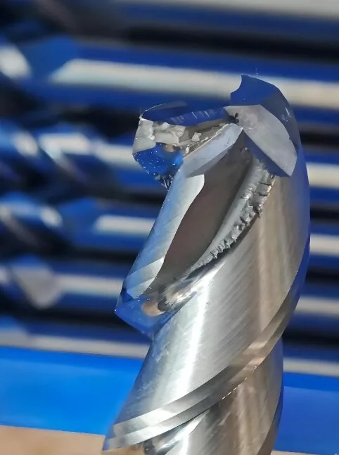
Chipping of milling cutters is a common failure affecting production efficiency and product quality in mechanical processing. As typical failure modes, tool tip chipping, middle cutting edge chipping, and large-area chipping have significant differences in their causes. Accurately distinguishing the inducing factors of these three types of chipping is crucial for quickly troubleshooting problems and optimizing processing technology. Combined with authoritative industry data, this article systematically analyzes the differences in the causes of the three types of chipping.

Milling cutter chipping

Core Definitions and Feature Distinctions

The three types of chipping have intuitive characteristic differences due to different failure locations and scopes, providing a basis for cause analysis:
  • Tool tip chipping: Concentrated in the tool tip arc and adjacent minor flank face areas, manifested as local tiny notches or fragmentation, belonging to localized failure.
  • Middle cutting edge chipping: Occurs in the middle section of the working length of the cutting edge, with the wear zone mostly showing uniform or irregular defects, not affecting the tool tip and both ends of the cutting edge.
  • Large-area chipping: Involves most areas of the cutting edge, often accompanied by blade surface spalling, crack propagation, and even partial tooth loss, belonging to global severe failure.

Differences in Causes of the Three Types of Chipping

Tool Tip Chipping: Stress Concentration and Local Load Overload

As the stress concentration area of the milling cutter during cutting, the tool tip has poor heat dissipation conditions and concentrated load-bearing. Its chipping is mainly caused by abnormal local loads:
  1. Improper matching of cutting parameters, such as excessively small feed rate leading to a sharp increase in load per unit area, or vertical cutting into hard workpieces resulting in instantaneous impact load.
  2. Defects in tool design, including excessively small tool tip arc radius and lack of transitional cutting edges, leading to insufficient cutting edge strength.
  3. Vibration of the process system, insufficient clamping rigidity of the workpiece or excessive runout of the machine tool spindle, causing the tool tip to bear alternating impact loads.
  4. Uneven workpiece material, encountering hard spots such as inclusions and sand holes during cutting, leading to local overload and chipping of the tool tip.

Middle Cutting Edge Chipping: Uniform Load Accumulation and Cutting Edge Strength Imbalance

Chipping in the middle of the cutting edge is mostly related to the uniform load during continuous cutting and the performance of the cutting edge itself:
  1. Problems with tool material or grinding quality, such as grinding microcracks and uneven hardness on the cutting edge, which gradually expand during continuous cutting.
  2. Unreasonable cutting parameters, excessively high cutting speed leading to thermal softening of the cutting edge, or excessively large cutting depth causing the middle cutting edge to bear excessive load for a long time.
  3. Poor chip evacuation, mismatching between chip breaker design and cutting parameters, leading to chip clogging and repeated friction on the middle cutting edge.
  4. Insufficient rigidity of the machine tool and fixture, causing cutting chatter and making the middle cutting edge bear alternating stress repeatedly and chip.

Large-Area Chipping: Extreme Conditions and Systematic Failure

Large-area chipping is a severe failure mode, usually caused by the superposition of multiple adverse factors or extreme cutting conditions:
  1. Extremely harsh cutting conditions, such as cutting parameters far exceeding the bearing limit of the tool, or frequent impact loads in intermittent cutting.
  2. Mismatch in basic tool performance, selecting tool materials with excessively high brittleness when processing hard and brittle materials, or blades having welding cracks and residual stress.
  3. Failure of cooling and lubrication, insufficient coolant flow or improper injection position, leading to a sharp rise in cutting edge temperature and a decrease in overall strength.
  4. Operational or process errors, such as not reserving tool retraction space when cutting out, or not cleaning burrs on the workpiece surface, causing global impact chipping.
The core causes of the three types of chipping can be summarized as follows: tool tip chipping focuses on "local load mutation and stress concentration", middle cutting edge chipping emphasizes "uniform load accumulation and cutting edge quality defects", and large-area chipping originates from "extreme cutting conditions and systematic matching imbalance". In actual production, the cause can be quickly located according to the chipping position and shape. The risk of chipping can be effectively reduced by optimizing tool selection, adjusting cutting parameters, and enhancing process rigidity.

This is the heading

Share to

This is the heading

Share to