

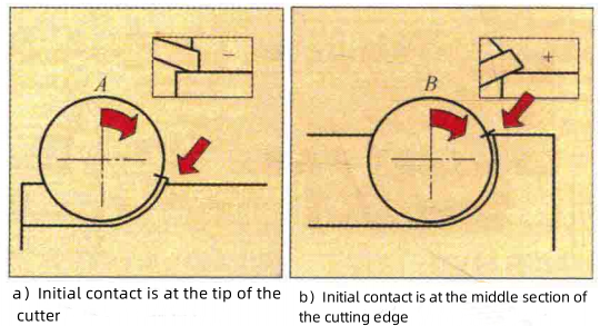
The cutting edge of a milling cutter undergoes an impact load, which varies in magnitude and direction, with each entry into the workpiece. This impact load is determined by the material of the workpiece, the cross-sectional area of the cut, and the type of milling operation. Such an impact load is a test for the cutting edge; if it exceeds the cutter's tolerance, the tool may break. Smooth initial contact between the milling cutter's cutting edge and the workpiece is a critical point in milling, which depends on the selection of the tool's diameter and geometric shape, as well as the positioning of the tool.
Figure A illustrates a successful initial contact method between the milling cutter's cutting edge and the workpiece. As shown in Figure A-a, the initial contact is at the tip of the cutting edge, which often occurs when the milling width is less than the radius of the milling cutter. In contrast, Figure A-b shows an initial contact at the middle section of the cutting edge, which typically happens when the milling width exceeds the radius of the milling cutter. Of course, the combination of rake angles of the milling cutter also affects the initial contact method at the tip, which will be discussed later.
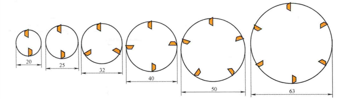
From experience, the relationship between milling width and tool diameter is typically between 2/3 (0.67) to 4/5 (0.8) (milling width to diameter ratio). This usually does not require specific calculation. Since milling cutter diameters generally conform to relevant standards, one can simply choose a milling cutter with a diameter not less than the second size above the predetermined milling width.
For example, as shown in Figure B, which is part of a series of milling cutter diameters (smaller diameters include 3mm, 4mm, 5mm, 6mm, 8mm, 10mm, 12mm, 16mm, etc., and larger diameters include 80mm, 100mm, 125mm, 160mm, 200mm, 250mm, 315mm, 400mm, etc.). Assuming the milling width is 36mm, the first size of diameter not less than this width is 40mm, and the second size is 50mm. The selected milling cutter disk diameter would be 50mm. However, if the milling width is exactly 40mm, the first size of diameter not less than this width is 40mm, and the second size is still 50mm, so the selected milling cutter disk diameter would also be 50mm.
During the milling process, precise control of the entry positioning is essential to prevent uneven cutting of the workpiece surface or unnecessary wear of the tool. Proper entry positioning ensures that each cutting edge of the milling cutter can effectively participate in the cutting process, thereby enhancing the machining efficiency and the quality of the workpiece surface.
To achieve accurate entry positioning, operators or CNC machine programmers need to consider factors such as the geometric shape of the milling cutter, the characteristics of the workpiece material, cutting parameters (such as speed and feed rate), and the dynamic performance of the machine tool. By integrating this information, the best entry strategy can be formulated to ensure the smooth progress of the milling process.
In practical applications, entry positioning typically involves the following aspects:
1. Entry Angle: This refers to the angle at which the milling cutter enters the workpiece surface. Depending on the machining requirements, the entry angle can be perpendicular, inclined, or radial.
2. Entry Point: This is the specific location where the milling cutter begins to make contact with the workpiece. Selecting an appropriate entry point can reduce sudden changes in cutting force and prevent damage to the workpiece or tool.
3. Entry Path: This refers to the trajectory of the milling cutter moving from the initial position to the entry point. The design of the entry path must take into account the geometric shape of the workpiece and the range of motion of the machine tool.
4. Entry Speed: This is the linear speed of the milling cutter when it contacts the workpiece. An appropriate entry speed can reduce the impact on the cutting edges and extend the tool life.
By precisely controlling these parameters, the quality and efficiency of the milling operation can be effectively improved. In modern CNC machine tools, these parameters are often automatically controlled through programming, achieving high precision and high efficiency in automated production.