
Vibration in milling can occur due to limitations of cutting tools, tool holders, machine tools, workpieces, or fixtures. To minimize vibration, several strategies should be considered.
1. Cutting Tools
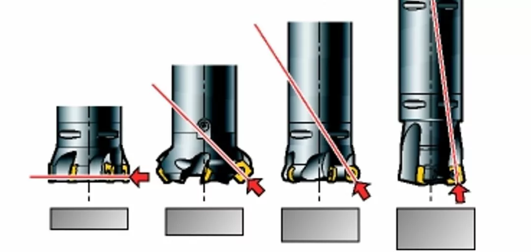
(1) For face milling, the direction of cutting forces must be considered:
-
When using a 90° milling cutter, cutting forces are mainly radial. This causes tool deflection in long overhang applications; however, low axial forces are advantageous when milling thin-walled/vibration-sensitive parts.
-
A 45° milling cutter generates evenly distributed axial and radial forces.
-
Round insert milling cutters direct most forces upward along the spindle, especially at small depths of cut. Additionally, 10° milling cutters transmit the main cutting forces into the spindle, reducing vibration from long tool overhangs.

-
Select the smallest possible diameter for the operation.
-
The tool diameter (DC) should be 20-50% larger than the radial depth of cut (ae).
-
Choose cutters with few flutes and/or unequal pitch.
-
Lightweight milling cutters are beneficial, such as those with aluminum alloy bodies.

For unstable thin-walled workpieces, use a large lead angle to achieve small axial cutting forces. For long tool overhangs, use a small lead angle to generate high axial cutting forces.
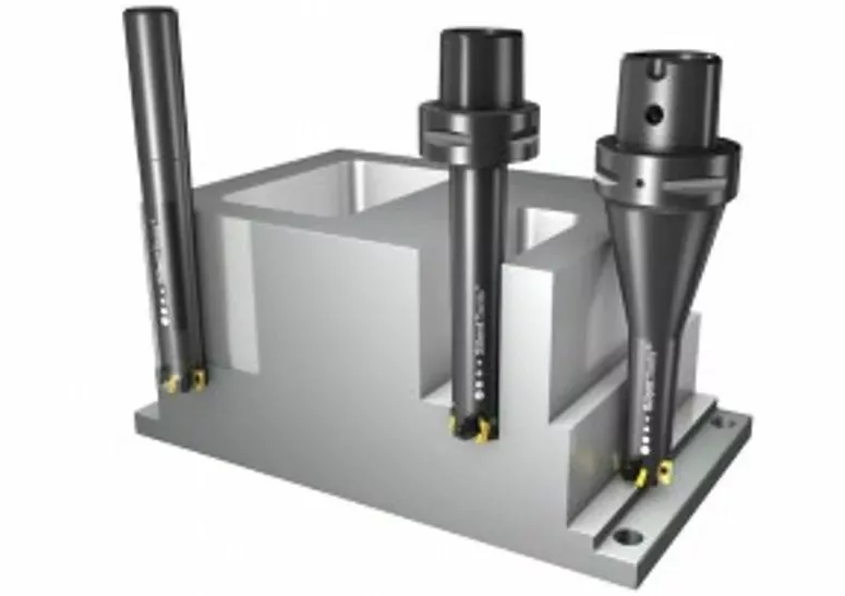
2. Tool Holders
Using the Coromant Capto® modular tooling system allows assembling tools of the required length while maintaining high stability and minimal runout.
- Keep the tool assembly as rigid as possible and as short as possible.
- Select the largest possible adapter diameter/size.
- Use Coromant Capto® adapters suitable for oversize milling cutters; avoid reducing adapters.
- For small-diameter cutters, use tapered adapters if possible.
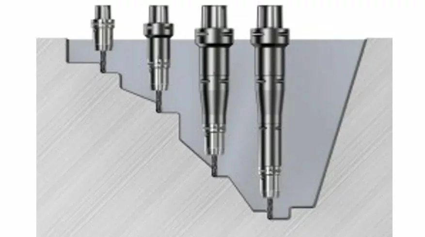
- In operations where the final cut is deep inside the part, switch to an extended tool at a predetermined position. Adjust cutting parameters according to each tool length.
- If the spindle speed exceeds 20,000 rpm, use dynamically balanced cutting tools and holders.
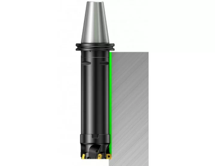
3. Vibration-Damping Cutters
If the overhang exceeds 4 times the tool diameter, milling vibration tends to become more pronounced. Silent Tools™ vibration-damping cutters can significantly improve productivity.
4. Cutting Edges
To reduce cutting forces:
- Select light-cutting geometries with sharp cutting edges (e.g., geometry L) and thin coating grades.
- Use inserts with small nose radii and narrow land widths.
In some cases, vibration tendency can be reduced by adding more damping to the system. Use cutting edge geometries with larger negative rake angles and slightly worn cutting edges.

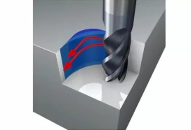
5. Cutting Parameters and Tool Path Programming
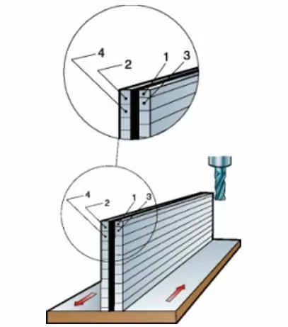
- Always position the milling cutter off-center relative to the milling surface.
- For KAPR 90° long-edge milling cutters or end mills, use small radial depth of cut (maximum ae = 25% × DC) and large axial depth of cut (maximum ap = 100% × De).
- For face milling, use small axial depth of cut (ap), high feed per tooth (fz), and round inserts or high-feed milling cutters with small lead angles.
- Avoid vibration in corners by programming large arc tool paths (see internal corner milling).
- If the chip thickness becomes too thin, the cutting edge will rub rather than cut, causing vibration. In this case, increase the feed per tooth.
6. Machine Tools
Machine tool condition can significantly affect milling vibration tendency. Excessive wear of spindle bearings or feed mechanisms will result in poor machining performance. Carefully select machining strategies and cutting force directions to fully utilize machine stability.
Each machine tool spindle has an unstable region prone to vibration. The stable cutting region is described by a stability diagram and increases with rotational speed. Even a speed increase as low as 50 rpm can transition the cutting process from an unstable vibrating state to a stable one.
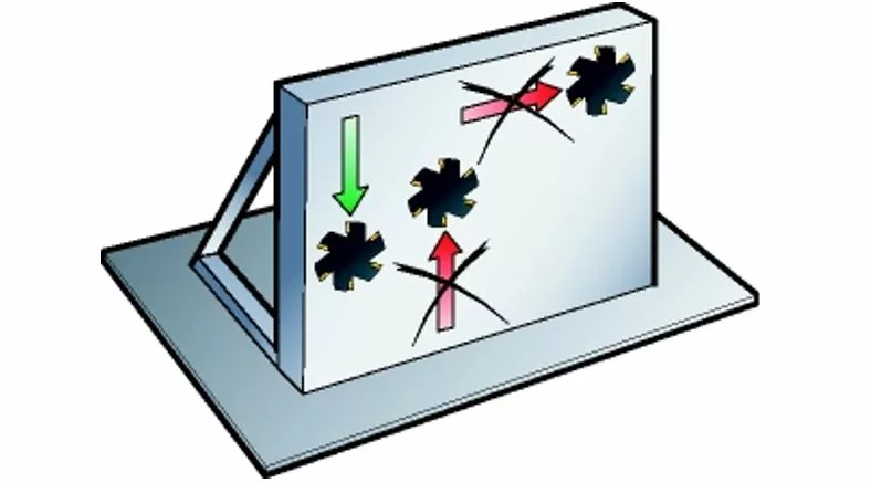
7. Workpieces and Their Fixtures
When milling thin-walled/base-mounted parts and/or using fixtures with poor rigidity, consider the following:
- Fixtures should be close to the machine tool table.
- Optimize tool paths and feed directions toward the positions with the highest machine/fixture rigidity to achieve the most stable cutting conditions.
- Avoid machining along directions where the workpiece is insufficiently supported.
- When fixtures and/or workpieces have poor rigidity in a specific direction, climb milling can reduce vibration tendency.
Note that the first cut should be performed at 1/2 the depth of the second cut, the second cut at 1/2 the depth of the third cut, and so on.