

1. Drilling
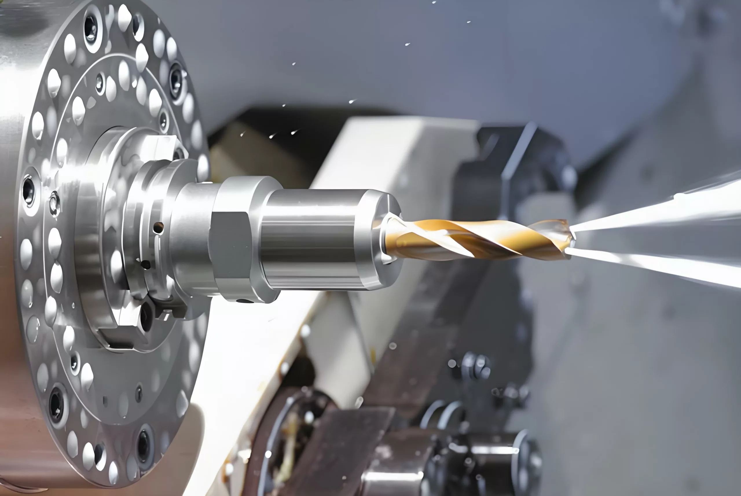
Drilling is the first process for creating holes in solid materials, with the drilled hole diameter typically less than 80mm. There are two drilling methods:
- One involves the drill bit rotating while the workpiece remains stationary.
- The other involves the workpiece rotating while the drill bit remains stationary.
The errors caused by these two methods differ. In the drill-rotating method, if the drill bit deflects due to asymmetric cutting edges or insufficient rigidity, the centerline of the machined hole will be skewed or unstraight, but the hole diameter remains essentially unchanged. In contrast, in the workpiece-rotating method, drill bit deflection leads to changes in the hole diameter, while the hole centerline remains straight.
Common drilling tools include twist drills, center drills, and deep-hole drills. Among them, twist drills are the most widely used, with diameter specifications ranging from Ф0.1mm to Ф80mm.
Due to structural limitations, drill bits have low bending and torsional rigidity, coupled with poor centering. As a result, drilling achieves relatively low accuracy, generally ranging from IT13 to IT11. The surface roughness is also relatively high, with Ra typically between 50μm and 12.5μm. However, drilling has a high metal removal rate and high cutting efficiency. It is mainly used for machining holes with low quality requirements, such as bolt holes, thread bottom holes, and oil holes. For holes requiring high accuracy and surface quality, subsequent processes like reaming, counterboring, boring, or grinding are necessary.
2. Reaming
Reaming is a process that uses a reamer to further machine holes that have been drilled, cast, or forged. It aims to enlarge the hole diameter and improve machining quality. Reaming can serve as either a pre-processing step before finish machining of holes or the final processing for holes with low requirements.
A reamer is similar to a twist drill but has more cutting teeth and no chisel edge. Compared with drilling, reaming has the following characteristics:
- Reamers have 3 to 8 teeth, providing good guidance and stable cutting.
- The absence of a chisel edge creates favorable cutting conditions.
- The machining allowance is small, allowing for shallower chip flutes and a thicker drill core, which enhances the tool body's strength and rigidity.
Reaming typically achieves an accuracy of IT11 to IT10, with a surface roughness Ra of 12.5μm to 6.3μm. It is commonly used for machining holes with diameters less than Ф100mm. When drilling large-diameter holes (D ≥ 30mm), a small drill bit (with a diameter 0.5 to 0.7 times the target hole diameter) is often used for pre-drilling, followed by reaming with a corresponding-sized reamer. This approach improves hole machining quality and production efficiency.
In addition to cylindrical holes, reaming can also be used to machine various counterbored seats and facing end surfaces using specially shaped reamers (also known as spotfacers). These spotfacers usually have a guide pin at the front, which is guided by the already machined hole.
3. Counterboring
Counterboring is one of the precision machining methods for holes and is widely used in production. For small holes, compared with internal grinding and precision boring, counterboring is a more economical and practical machining method.
3.1 Counterbores
Counterbores are generally divided into two types: hand counterbores and machine counterbores.
- Hand counterbores have a straight shank and a long working part, providing good guiding performance. They are available in both solid and externally adjustable structures.
- Machine counterbores come in two structures: shanked and shell-type.
Counterbores can not only machine circular holes but also tapered holes using taper counterbores.
3.2 Counterboring Process and Its Application
The counterboring allowance has a significant impact on counterboring quality.
- Excessive allowance increases the load on the counterbore, quickly dulling the cutting edges. This makes it difficult to obtain a smooth machined surface and ensure dimensional tolerance.
- Insufficient allowance fails to remove tool marks left by the previous process, thus not improving the hole machining quality.
Generally, the rough counterboring allowance ranges from 0.35mm to 0.15mm, and the finish counterboring allowance ranges from 0.1mm to 0.05mm.
To avoid the formation of built-up edges, counterboring is usually performed at a low cutting speed (for high-speed steel counterbores machining steel and cast iron, v < 8m/min). The feed rate depends on the machined hole diameter; the larger the hole diameter, the higher the feed rate. When machining steel and cast iron with high-speed steel counterbores, the feed rate is typically 0.3mm/r to 1mm/r.
During counterboring, an appropriate cutting fluid must be used for cooling, lubrication, and chip cleaning to prevent built-up edge formation and remove chips promptly. Compared with hole grinding and boring, counterboring has higher productivity and easily ensures hole accuracy. However, counterboring cannot correct the positional error of the hole axis, so the positional accuracy of the hole must be guaranteed by the previous process. Counterboring is not suitable for machining stepped holes or blind holes.
Counterboring typically achieves a dimensional accuracy of IT9 to IT7, with a surface roughness Ra of 3.2μm to 0.8μm. For medium-sized holes with high accuracy requirements (e.g., holes with IT7 accuracy), the drill-ream-counterbore process is a typical and commonly used machining scheme in production.
4. Boring
Boring is a machining method that uses a cutting tool to enlarge a prefabricated hole. It can be performed either on a boring machine or a lathe.
4.1 Boring Methods
There are three different boring methods:
- Workpiece rotation, tool feed movement: Most boring operations on lathes fall into this category. Its process characteristics are that the axis of the machined hole is consistent with the rotation axis of the workpiece. The roundness of the hole mainly depends on the rotational accuracy of the machine tool spindle, and the axial geometric error of the hole mainly depends on the positional accuracy of the tool feed direction relative to the workpiece rotation axis. This boring method is suitable for machining holes that require coaxiality with the outer cylindrical surface.
- Tool rotation, workpiece feed movement: The boring machine spindle drives the boring tool to rotate, and the worktable drives the workpiece to perform feed movement.
- Tool rotation with simultaneous feed movement: When using this boring method, the overhang length of the boring bar changes, leading to varying deflection of the boring bar. As a result, the hole diameter is larger near the spindle box and smaller away from it, forming a tapered hole. Additionally, as the overhang length of the boring bar increases, the bending deformation of the spindle due to its own weight also increases, causing a corresponding bending of the machined hole axis. This boring method is only suitable for machining short holes.
4.2 Diamond Boring
Compared with ordinary boring, diamond boring is characterized by small back cutting depth, small feed rate, and high cutting speed. It can achieve high machining accuracy (IT7 to IT6) and a very smooth surface (Ra of 0.4μm to 0.05μm). Initially, diamond boring used diamond boring tools, but now cemented carbide, CBN (cubic boron nitride), and synthetic diamond tools are commonly used. It is mainly used for machining non-ferrous metal workpieces, but can also be used for machining cast iron parts and steel parts.
The common cutting parameters for diamond boring are as follows:
- Back cutting depth: 0.2mm to 0.6mm for pre-boring, and 0.1mm for final boring.
- Feed rate: 0.01mm/r to 0.14mm/r.
- Cutting speed: 100m/min to 250m/min for machining cast iron, 150m/min to 300m/min for machining steel, and 300m/min to 2000m/min for machining non-ferrous metals.
To ensure that diamond boring achieves high machining accuracy and surface quality, the machine tool used (diamond boring machine) must have high geometric accuracy and rigidity. The spindle bearings of the machine tool usually use precision angular contact ball bearings or hydrostatic sliding bearings, and high-speed rotating parts must undergo precise balancing. Additionally, the movement of the feed mechanism must be very stable to ensure that the worktable can perform stable low-speed feed movement.
Diamond boring offers good machining quality and high production efficiency. It is widely used in mass production for the final machining of precision holes, such as engine cylinder holes, piston pin holes, and spindle holes on machine tool headstocks. However, it should be noted that when machining ferrous metal products with diamond boring, only cemented carbide and CBN boring tools can be used, not diamond tools. This is because the carbon atoms in diamond have a strong affinity with iron group elements, resulting in low tool life.
4.3 Boring Tools
Boring tools can be divided into single-edged boring tools and double-edged boring tools.
4.4 Process Characteristics and Application Scope of Boring
Compared with the drill-ream-counterbore process, the hole diameter in boring is not limited by the tool size. Boring also has a strong error correction capability, allowing correction of the original hole axis deflection error through multiple passes. Moreover, it can maintain high positional accuracy between the bored hole and the positioning surface.
Compared with external cylindrical turning, boring has lower machining quality and production efficiency. This is because the boring bar system has poor rigidity and large deformation, unfavorable heat dissipation and chip evacuation conditions, and significant thermal deformation of the workpiece and tool.
In summary, boring has a wide machining range and can process holes of various sizes and accuracy grades. For large-diameter holes and hole systems with high requirements for size and positional accuracy, boring is almost the only machining method. Boring achieves an accuracy of IT9 to IT7, with a low surface roughness Ra. It can be performed on machine tools such as boring machines, lathes, and milling machines, offering flexibility and wide application in production. In mass production, boring jigs are often used to improve boring efficiency.
5. Honing
5.1 Honing Principle and Honing Head
Honing is a finishing method that uses a honing head equipped with abrasive sticks (oilstones) to machine holes. During honing, the workpiece is fixed, and the honing head is driven by the machine tool spindle to rotate and perform reciprocating linear movement. In the honing process, the abrasive sticks act on the workpiece surface with a certain pressure, removing an extremely thin layer of material from the workpiece surface. The cutting path forms intersecting reticulate patterns.
To ensure that the movement path of the abrasive grains on the honing head does not repeat, the number of revolutions per minute of the honing head's rotational movement and the number of reciprocating strokes per minute of the honing head must be coprime numbers.
The intersection angle θ of the honing path is related to the reciprocating speed (va) and the circumferential speed (vc) of the honing head. The size of the θ angle affects the honing quality and efficiency. Generally, θ = 40° to 60° for rough honing, and a smaller angle is used for finish honing. To facilitate the discharge of broken abrasive grains and chips, reduce cutting temperature, and improve machining quality, an adequate amount of cutting fluid should be used during honing.
To ensure uniform machining of the entire wall of the machined hole, the stroke of the abrasive sticks must extend beyond the hole at both ends by a certain overtravel. To ensure uniform honing allowance and reduce the impact of machine tool spindle runout on machining accuracy, a floating connection is mostly used between the honing head and the machine tool spindle.
The radial expansion and contraction adjustment of the abrasive sticks on the honing head can be achieved through various structures, such as manual, pneumatic, and hydraulic.
5.2 Process Characteristics and Application Scope of Honing
- Honing can achieve high dimensional accuracy and shape accuracy, with a machining accuracy of IT7 to IT6. The roundness and cylindricity errors of the hole can be controlled within a small range. However, honing cannot improve the positional accuracy of the machined hole.
- Honing can achieve high surface quality, with a surface roughness Ra of 0.2μm to 0.025μm. The depth of the metamorphic defect layer on the surface metal is extremely small (2.5μm to 25μm).
- Compared with grinding speed, the circumferential speed of the honing head is not high (vc = 16m/min to 60m/min). However, due to the large contact area between the abrasive sticks and the workpiece and the relatively high reciprocating speed (va = 8m/min to 20m/min), honing still has high productivity.
Honing is widely used in mass production for machining precision holes in engine cylinder bores and various hydraulic devices. The diameter range of the holes is generally larger, and it can machine deep holes with a length-to-diameter ratio greater than 10. However, honing is not suitable for machining holes in non-ferrous metal workpieces with high plasticity, nor can it machine holes with keyways, spline holes, etc.
6. Broaching
6.1 Broaching and Broaches
Broaching is a high-productivity precision machining method that uses a specially designed broach on a broaching machine. Broaching machines are divided into horizontal broaching machines and vertical broaching machines, with horizontal broaching machines being the most common.
During broaching, the broach only performs low-speed linear movement (main movement). The number of teeth of the broach working simultaneously should generally not be less than 3; otherwise, the broach will work unsteadily, easily producing annular ripples on the workpiece surface. To avoid excessive broaching force that may cause the broach to break, the number of teeth of the broach working simultaneously should generally not exceed 6 to 8.
There are three different broaching methods, as described below:
- Layered broaching: The characteristic of this broaching method is that the broach removes the machining allowance of the workpiece layer by layer in sequence. To facilitate chip breaking, the tool teeth are ground with staggered chip splitters. Broaches designed according to the layered broaching method are called ordinary broaches.
- Block broaching: In this broaching method, each layer of metal on the machined surface is removed by a group of teeth with basically the same size but staggered (usually 2 to 3 teeth per group). Each tooth only removes a part of a layer of metal. Broaches designed according to the block broaching method are called rotary-cut broaches.
- Comprehensive broaching: This method combines the advantages of layered and block broaching. The rough cutting teeth adopt block broaching, and the finish cutting teeth adopt layered broaching. This not only shortens the length of the broach and improves productivity but also achieves better surface quality. Broaches designed according to the comprehensive broaching method are called comprehensive broaches.
6.2 Process Characteristics and Application Scope of Broaching
- A broach is a multi-tooth tool. It can sequentially complete the rough machining, finish machining, and finishing of holes in a single broaching stroke, resulting in high production efficiency.
- The broaching accuracy mainly depends on the accuracy of the broach. Under normal conditions, broaching can achieve an accuracy of IT9 to IT7, with a surface roughness Ra of 6.3μm to 1.6μm.
- During broaching, the workpiece is positioned by the machined hole itself (the front guide part of the broach serves as the positioning element for the workpiece). Broaching makes it difficult to ensure the mutual positional accuracy between the hole and other surfaces. For rotating parts that require coaxiality between the inner and outer cylindrical surfaces, broaching is often performed first, followed by machining other surfaces using the hole as the positioning reference.
- Broaches can not only machine circular holes but also shaped holes and spline holes.
- Broaches are fixed-size tools with complex shapes and high prices, making them unsuitable for machining large holes.
Broaching is commonly used in mass production for machining through holes with diameters of Ф10mm to 80mm and a depth not exceeding 5 times the hole diameter in small and medium-sized parts.